Apparatus
This page provides details about the apparatus used to collect data for the PHM09 Data Challenge.
Gearbox
The data presented here is representative of generic industrial gearbox data. Figure 1 is a schematic of the gearbox used to collect the data.
Figure 1: Schematic of the apparatus (click to enlarge).
Two geometries are used,one using a spur gears, the other using spiral cut (helical) gears. The spur geometry is:
- Input shaft: 1-Input Pinion: 32 teeth
- Idler shaft: 1st idler gear: 96 teeth
- Idler shaft: 2nd (output) idler gear: 48 teeth
- Output shaft: output pinion: 80 teeth
Thus, from input to output the gear reduction ratio is: 16/48*24/40, or 5 to 1 reduction.
Acquisition System
Endevco 10mv/g Accel, +/- 1% error, Resonance > 45KHz.
Three Channels:
- Channel 1 is the input side Accelerometer
- Channel 2 is the output side Accelerometer
- Channel 3 is the Tachometer Signal: 10 pulse per revolution
Sample Rate: 66,666.67 Samples per Second (200 KHz/3).
Bearing
MB Manufacturing ER-10K
Number of Elements: 8
Roller Element Diameter: 0.3125″
Pitch Diameter: 1.319″
Contact Angle: 0
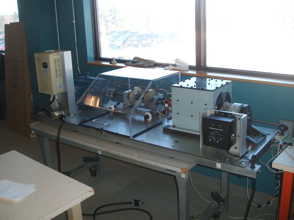
Figure 2: Overview of the apparatus (click to enlarge).
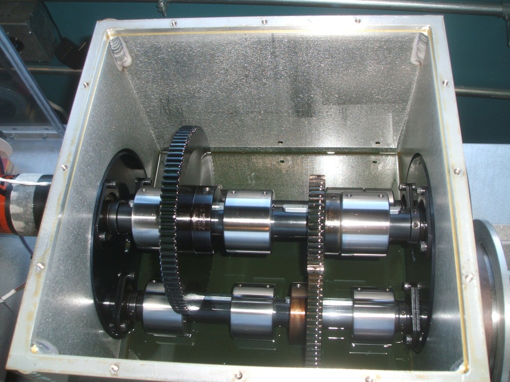
Figure 3: Inside the gearbox (click to enlarge).
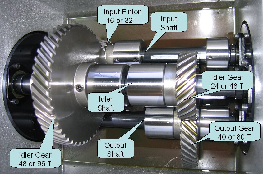
Figure 3a: Inside the gearbox detail (click to enlarge).
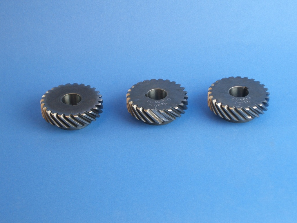
Figure 4: Example of gear faults. Left to right: normal, missing tooth, chipped tooth (click to enlarge).
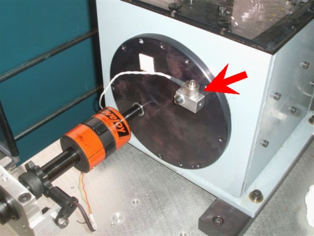
Figure 5: Location of input shaft accelerometer.
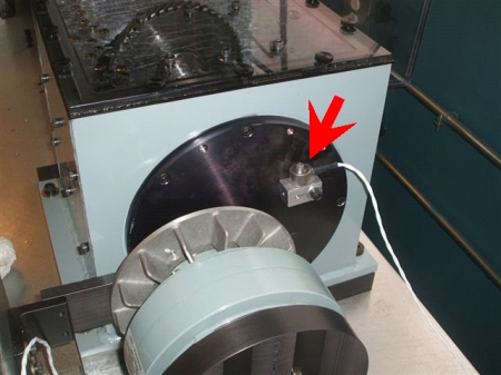
Figure 6: Location of output shaft accelerometer.
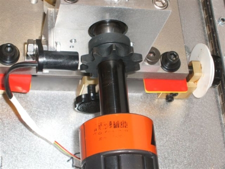
Figure 7: Detail of tachometer pickup.
A video of the system being run can be downloaded here. The change in gearbox tone is a function of the brake being applied.